SOFC
HELP Design
HELP Applications
Appendix
Fuel Cells in General
SOFC's in General
HELP Design (Hollow Electrodes Loose Plates)
A novel SOFC design has been invented and patented, targeted on using existing and therefore economic ceramic production techniques. Goal is achieving a significantly more reliable SOFC and a shortened product development.
In essence, it is a planar AND tubular SOFC with the combined advantages of both designs.

Untill now, in spite of a lot of development work, SOFC market introduction has not occurred yet due to expansion and material compatibility problems related to sinter bonding and/or incompatibility of the different materials. Please refer to the appendices
1 (Fuel Cells in General) and 2 (SOFC's in general) if you require general information on existing fuel cells.
Our SOFC design offers an opportunity to avoid these sinter bond related difficulties by omitting sinter bonding in the first place. This is realized by application of loose stacking of the cell elements, enabling free thermal expansion. This new design concept can be put into SOFC practice by application of the following measures:
- Production of the individual loose SOFC elements comprising hollow electrodes (a kind of planar tubes) comprising a dense outer layer, enabling safe gas flow management similar to a tubular SOFC.
Also the electrolyte- and interconnect sheets are produced.
This can be followed by early testing.
With HELP, production occurs using only one single material per element, which is significantly less complex than sinter bonding of multiple materials and enables material recycling. - Loose stacking of the hollow electrodes, electrolyte- and interconnect sheets into a cell. Several cell units thus form a loose cell stack.
- This allows for free thermal expansion of the fuel cell elements during thermal cycling and operation by this loose cell stacking
Note that differences in thermal expansion do not result in mechanical stress and in cracking. As a result of this, SOFC materials do not have to be adjusted for their thermal expansion behaviour. This greatly increases the freedom of material choice and reduces the development work on material compatibility enabling direct application of new anode materials for direct internal reforming (DIR).
The following animation for application in cable TV systems shows the working principle of direct reforming in our SOFC fuel cell:
The electrochemistry of this new SOFC type is very similar to conventional SOFC designs. A more detailed detailed cross-section of a single cell showing the electrochemical phenomena is shown in the following figure :
- Step 1: Ionisation of O2 into O2- in the cathode
- Step 2: Migration of O2- through cathode electrolyte and anode dense layers
- Step 3: Reaction of O2- with (reformed) H2 and/or CO
- Step 4: Transfer of electrons through the interconnect to the next cell
The electrodes basically consist of flattened tubes having the advantage of a tubular design in gas connection, when compared to planar SOFC designs. The electrical efficiency of this design is expected to be at least similar to that of conventional designs. Initial measurements have shown quite surprisingly that virtually no losses occur at properly made loose contacts.
Contrary to conventional designs, the electrolyte and interconnect sheets do not have a function as gas separator nor are in direct contact with any of the gases. Therefore the sheets can be applied significantly thinner than in the conventional designs, enabling improved electrical efficiency.
--> Note that the fact that the interconnect sheet is no longer in contact with either of the gases eliminates the material compatibility problems related to contacting both the air and fuel gases as in all other designs!
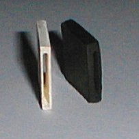
Samples of experimental hollow electrodes comprising a dense membrane structure are shown in the next figure:
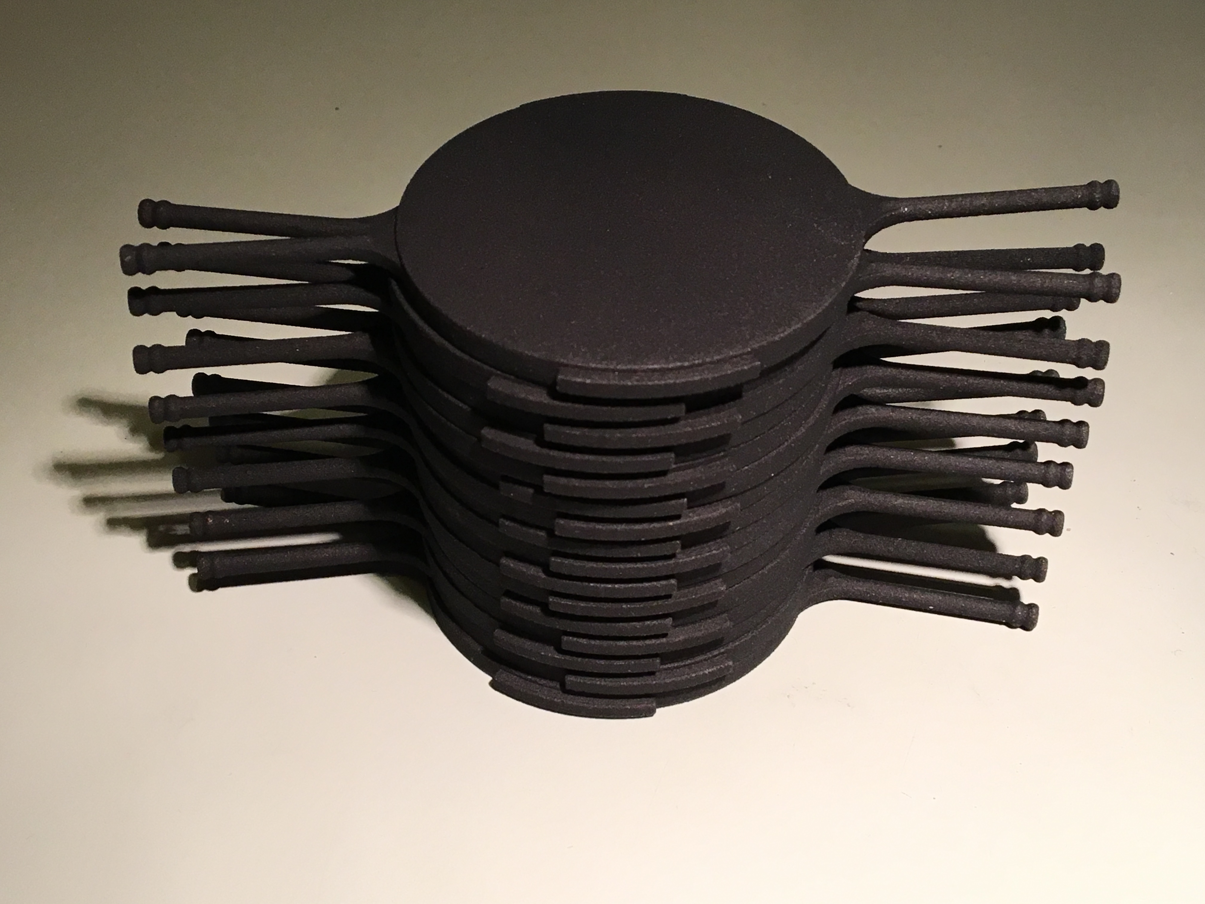
And a model view on how an SOFC-HELP stack is arranged:
Summary: A possible step-change exists to fundamentally improve production of reliable SOFC's with a similar or higher electrical efficiency. This is achieved by:
- Use of low-cost existing injection molding production methods.
- Virtual total freedom of material choice, which avoids expensive rare earth metals
- Very much lower CAPEX cost per unit
- Application of new material for direct internal reforming (DIR) for fuel flexibiity
- A shortened development serving many commercial applications
- Fast development to a mass scale, thus short time to market
- Enables material recycling due to loosely stacked elements.
Resulting in: